Currently, the UNICAN emulator supports the following immobiliser systems that communicate via CAN bus:
| VEHICLE BRAND AND GENERATION OF IMMO SYSTEM: |
BYTE CONFIG VALUE ADDRESS 0x02: |
BYTE CANBUS SPEED ADDRESS 0x01: |
|
|
|
| RENAULT |
0xFF – AUTO DETECTS IMMO SYSTEM |
250/500 – values : 0x25, 0x50 |
| RENAULT DATA COLLECTION FOR CALCULATION ISK |
0x52 – MANUAL SELECTION |
500 – values : 0x50 |
| PSA |
0xFF – AUTO DETECTS IMMO SYSTEM |
250/500 – values : 0x25, 0x50 |
| PSA TCU AXN8 |
0x06 – MANUAL IMMO SYSTEM SELECTION |
500 – values : 0x50 |
| FIAT/IVECO |
0xFF – AUTO DETECTS IMMO SYSTEM |
50/250/500 – values : 0x05, 0x25, 0x50 |
| NISSAN NATS6/7 |
0xFF – AUTO DETECTS IMMO SYSTEM |
500 – values : 0x50 |
| MERCEDES FBS2 |
0xFF – AUTO DETECTS IMMO SYSTEM |
500/125 – values : 0x50, 0x12 |
| MERCEDES FBS3 CR2 EDC15 ONLY |
0xFF – AUTO DETECTS IMMO SYSTEM |
500 – values : 0x50 |
| VAG WFS3 |
0xFF – AUTO DETECTS IMMO SYSTEM |
500 – values : 0x50 |
| VAG WFS4 |
0xFF – AUTO DETECTS IMMO SYSTEM |
500 – values : 0x50 |
| VAG WFS5/MQB ECU & TCU |
0x01 – MANUAL IMMO SYSTEM SELECTION |
500 – values : 0x50 |
| SMART FORTWO W450 REMOTE IMMO SYSTEM |
0x02 – MANUAL IMMO SYSTEM SELECTION |
500 – values : 0x50 |
| BMW EWS4 (SWAP ENGINE) |
0x03 – MANUAL IMMO SYSTEM SELECTION |
500 – values : 0x50 |
| BMW EWS4 (SWAP GEARBOX) |
0x04 – MANUAL IMMO SYSTEM SELECTION |
500 – values : 0x50 |
| MITSUBISHI COLT / SMART FORTWO W451 / SMART FORFOUR |
0x02 – MANUAL IMMO SYSTEM SELECTION |
500 – values : 0x50 |
| FORD WFS2 TRANSIT MK7 DCU10X DCU20X DCU212 |
0x05 – MANUAL IMMO SYSTEM SELECTION |
500 – values : 0x50 |
| FORD WFS1 CANBUS FOCUS 2 / MAZDA3 |
0x07 – MANUAL IMMO SYSTEM SELECTION |
500 – values : 0x50 |
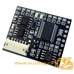
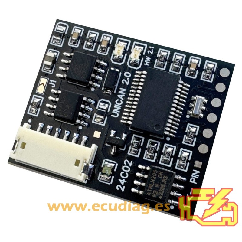
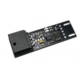
The current program is selected by writing the BYTE CONFIG VALUE to the address 0x02 in the I2C 24C02 eeprom installed on the emulator PCB.
The Can bus speed program is selected by writing the CANBUS SPEED value byte to the address 0x01 in the I2C 24C02 eeprom installed on the emulator PCB.
For proper operation, the synchronisation data retrieved from the ECU must be stored in the 24c02 memory of this emulator, the address from which we store this data is 0x10.
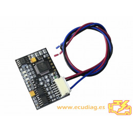
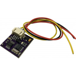
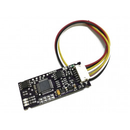
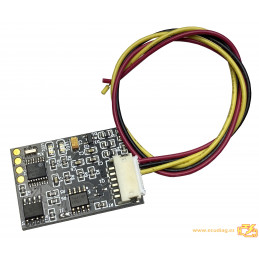
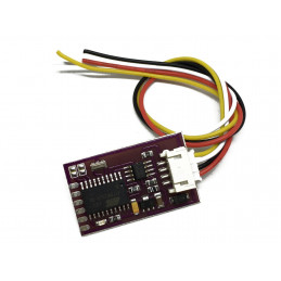
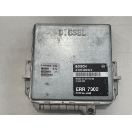
Four wires should be connected: CAN-H, CAN-L, GND (ground) and +12 V IGN ( terminal „15”) or +12 V after the ECU/ECM relay.
Ensure the connection adheres to the vehicle’s electrical repair schematics.
ECU WIRING:
| YELLOW CABLE |
CAN H |
| WHITE CABLE |
CAN L |
| RED CABLE |
+12V (15) |
| BLACK CABLE |
GND |
You can download user manual in the attachments option.
EcuDiag is not responsible for the improper use of the emulators or for damage caused by improper assembly and manipulation of the ecu. We recommend using the emulators to unlock the immobilizer system when the vehicle does not start to be able to move it to the workshop for repair the immobilizer system.